Particle Materials
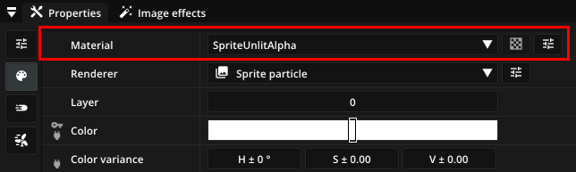
Materials define the appearance of particles and how they interact with lights. The material of a particle type can be set in the Visual tab in the Properties window. Most materials offer additional material parameters like a texture or an emission color, which can be set by clicking next to the material property. Pixelpart has several built-in materials but you can also define custom materials using shader graphs.
Built-in materials
Pixelpart’s built-in materials are suitable for a variety of circumstances and most of the time you do not need to create custom materials. The built-in materials provide support for texturing, sprite sheet animation, lighting, soft particles and more. Depending on the renderer you have selected for a particle type, you can choose from different built-in materials.
Sprite materials
The following materials are available for Sprite particles.
Material |
Description |
|---|---|
SpriteUnlitAlpha |
For rendering alpha-blended sprite particles without lighting. |
SpriteUnlitAdditive |
For rendering additively blended sprite particles without lighting. |
SpriteLitAlpha |
For rendering alpha-blended sprite particles with lighting. |
SpriteLitAdditive |
For rendering additively blended sprite particles with lighting. |
All of these materials provide support for sprite sheet animation, soft particles and distance fade.
Trail materials
The following materials are available for Trail particles.
Material |
Description |
|---|---|
TrailUnlitAlpha |
For rendering alpha-blended trail particles without lighting. |
TrailUnlitAdditive |
For rendering additively blended trail particles without lighting. |
TrailLitAlpha |
For rendering alpha-blended trail particles with lighting. |
TrailLitAdditive |
For rendering additively blended trail particles with lighting. |
All of these materials provide support for soft particles and distance fade.
Mesh materials
The following materials are available for Mesh particles.
Material |
Description |
|---|---|
MeshUnlit |
For rendering opaque mesh particles without lighting. |
MeshUnlitAlpha |
For rendering alpha-blended mesh particles without lighting. |
MeshLit |
For rendering opaque mesh particles with lighting. |
MeshLitAlpha |
For rendering alpha-blended mesh particles with lighting. |
Custom materials
Warning
Custom materials are not fully supported across all game engine plugins. Stick to built-in materials to make sure particles are rendered correctly in all engines.
To start creating a custom material for a particle type, select the New option in the material drop-down menu of the particle type and then click next to the material property, which opens the Material editor.
Custom material are designed with shader graphs allowing you to define the material of particles more precisely. Such a shader graph consists of nodes that work together to define the final pixel color. Each nodes implements a specific function that computes an output value from its input values, which are supplied by other nodes. Some nodes also have additional parameters that influence their function.
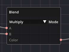
One example is the Blend node, which mixes two colors together: The two colors are connected to the input pins of the node while the output pin, carrying the resulting color, is connected to other nodes in the graph. The parameter Mode determines how the colors are blended together.
Eventually, all nodes run together into the Output node, which sets the final color of each pixel. Color values are stored in RGBA (Red, Green, Blue, Alpha) format, where each channel contains a number in the range [0, 1] defining the color intensity for that channel. The alpha component defines the opacity. The node also has inputs for an emission color, as well as a roughness and metallic values used during shading of the particle in the presence of light.
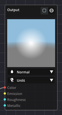
Inside the Output node you also set the blend mode and lighting mode of the material. The blend mode determines how particles are blended together and are composed with other objects in the effect.
Off: Particles are not blended together and occlude each other.
Normal: Particles are blended together based on their opacity.
Additive: Particle colors are added together.
Subtractive: Particle colors are subtracted from each other.
The lighting mode determines whether the material is shaded by lights in the scene.
Unlit: The material is not shaded based on lighting.
Lit: The material is shaded based on lighting.
Creating shader graphs
By default, a custom material already has a default shader graph, which applies a texture and combines it with the color set in the particle properties. To assign a completely new material click New or select a preset from the drop-down menu. The name of the material can be set in the input field in the toolbar.
You can add new nodes by dragging a node from the toolbox on the right and dropping it on the shader graph or by clicking Add in the toolbar. The list of available nodes can be filtered by typing in the search box at the top.
Another way to create nodes is to drag out a node pin and then letting go. This will show a popup of available nodes. After selecting a node type, a new node is created. Using this method, there are several keyboard shortcuts for creating common node types directly.
Shortcut |
Node |
|---|---|
1 |
Number |
2 |
Vector 2 |
3 |
Vector 3 |
4 |
Vector 4 |
B |
Boolean |
I |
Integer |
C |
Color |
After adding a new node, connect its input and output pins to the rest of the graph by dragging out links from each pin. The pin color and shape denote the data type that is expected for the attribute. For example, the red color denotes a 4-component vector, which is used for color values. Most of the time, different data types can be converted into one another.
To remove a node, select the node(s) and press Del or click Remove in the tool bar.
In order to apply your changes to the material, click Apply in the toolbar. Otherwise, they are discarded when you close the window.
Saving and loading materials
You can save a custom material to a .ppmt file, which is useful for sharing materials across different effects. Click Save in the toolbar to select a location for the material file. An existing material file can be loaded using Load.
Available nodes
Constants
Node |
Inputs |
Description |
|---|---|---|
Boolean |
Boolean constant, which can be true or false. |
|
Integer |
Integer constant, which can be any positive or negative integer. |
|
Number |
Number constant, which can be any rational number. |
|
Vector 2 |
Vector constant with two components. |
|
Vector 3 |
Vector constant with three components. |
|
Vector 4 |
Vector constant with four components. |
|
Color |
Color constant with four components (RGBA). |
Inputs
Node |
Inputs |
Description |
|---|---|---|
Input: Position (world space) |
Vertex position in world space. |
|
Input: Position (view space) |
Vertex position in view space. |
|
Input: Normal (world space) |
Normal at the current pixel in world space. |
|
Input: Normal (view space) |
Normal at the current pixel in view space. |
|
Input: Texture coordinate |
Texture coordinate at the current pixel. Used to sample textures. |
|
Input: Color |
Color of the particle. This input can be set with the Color attribute in the Visuals tab. |
|
Input: Velocity |
Velocity vector of the particle. |
|
Input: Life |
Remaining life of the particle, from 1.0 (particle has just spawned) to 0.0 (particle is about to disappear). |
|
Input: Object ID |
ID of the current particle, which can be used to differentiate individual particles. |
|
Effect time |
Time passed since the effect has started. |
|
Object time |
Time passed since the particle emitter was instantiated. |
Colors
Node |
Inputs |
Description |
|---|---|---|
Blend |
A, B |
Blends colors A and B together using the specified blending mode. |
Color ramp |
Value |
Picks a color from the specified gradient using Value as an index between 0.0 and 1.0. |
Adjust brightness |
Color, Brightness |
Increases the brightness of Color for Brightness > 0 and decreases it for Brightness < 0. |
Adjust exposure |
Color, Exposure |
Increases the exposure of Color for Exposure > 0 and decreases it for Exposure < 0. |
Adjust contrast |
Color, Contrast |
Increases the contrast of Color for Contrast > 0 and decreases it for Contrast < 0. |
Adjust saturation |
Color, Saturation |
Increases the saturation of Color for Saturation > 0 and decreases it for Saturation < 0. |
Posterize |
Color, Number |
Reduces the number of available colors per channel to Number. |
Textures
Node |
Inputs |
Description |
|---|---|---|
Texture: Image |
UV |
Samples the given image at texture coordinate UV. |
Texture: Sprite sheet |
UV, Frame |
Samples the sprite at index Frame in the given sprite sheet at texture coordinate UV. |
Sprite sheet |
UV, Frame, Frames / row, Frames / column |
Calculates the corresponding texture coordinate for sampling a sprite sheet at index Frame. |
Tiling and offset |
UV, Tiling, Offset |
Transforms texture coordinate UV by tiling it Tiling times and applying Offset. |
Twirl |
UV, Amount |
Transforms texture coordinate UV by twirling it with strength Amount. |
Procedural
Node |
Inputs |
Description |
|---|---|---|
Circle mask |
UV, Radius, Smoothness |
Generates a circular mask, where (0.5, 0.5) is the circle’s center, Radius is its radius and Smoothness dictates how slowly the value falls off outside the radius. The circle is then sampled at coordinate UV. |
Noise (1D) |
Position, Amplitude, Frequency, Persistence, Lacunarity |
Generates 1D Simplex noise with the given parameters. This noise is sampled at coordinate Position. |
Noise (2D) |
Position, Amplitude, Frequency, Persistence, Lacunarity |
Generates 2D Simplex noise with the given parameters. This noise is sampled at coordinate Position. |
Math
Node |
Inputs |
Description |
|---|---|---|
Add |
A, B |
Adds A and B (A + B). |
Subtract |
A, B |
Subtracts B from A (A - B). |
Multiply |
A, B |
Multiplies A with B (A * B). |
Divide |
A, B |
Divides A by B (A / B). |
Modulo |
A, B |
Computes the modulus of A and B (A mod B). |
Power |
A, B |
Raises A to the power of B (A^B). |
Natural exponentiation |
Value |
Computes the natural exponentiation of Value (exp(Value)). |
Natural logarithm |
Value |
Computes the natural logarithm of Value (ln(Value)). |
Sign |
Value |
Returns the sign of Value, i.e. +1 if Value is positive, -1 if Value is negative and 0 if Value is 0. |
Absolute value |
Value |
Returns the absolute value of Value (|Value|). |
Min |
A, B |
Returns the minimum of A and B (min(A, B)). |
Max |
A, B |
Returns the maximum of A and B (max(A, B)). |
Clamp |
Value, Min, Max |
Limits Value to the range [Min, Max]. |
Linear interpolation |
A, B, Factor |
Interpolations linearly between A and B using Factor (in the range [0, 1]). |
Floor |
Value |
Rounds Value down to the next integer. |
Ceil |
Value |
Rounds Value up to the next integer. |
Round |
Value |
Rounds Value to the nearest integer. |
Square root |
Value |
Computes the square root of Value. |
Sin |
Value |
Computes the sine of Value. |
Cos |
Value |
Computes the cosine of Value. |
Arcsin |
Value |
Computes the arcus sine of Value. |
Arccos |
Value |
Computes the arcus cosine of Value. |
Dot product |
A, B |
Computes the dot product of vectors A and B. |
Cross product |
A, B |
Computes the cross product of vectors A and B. |
Normalize |
Vector |
Normalizes Vector to a vector of length 1. |
Vector length |
Vector |
Returns the length or magnitude of Vector. |
Step |
Value, Edge |
Generates a step function by comparing Value to Edge. If Value < Edge, the output is 0 and otherwise 1. |
Smooth step |
Value, Edge 1, Edge 2 |
Performs a smooth interpolation between 0 and 1 when Edge 1 < Value < Edge 2. |
Threshold |
Value |
Returns parameter Output if Value is smaller than parameter Threshold. |
Logic
Node |
Inputs |
Description |
|---|---|---|
Negation (NOT) |
Value |
Negates the boolean Value. |
Conjunction (AND) |
A, B |
Outputs true if and only if both A and B are true. |
Disjunction (OR) |
A, B |
Outputs true if and only if A or B is true. |
Exclusive disjunction (XOR) |
A, B |
Outputs true if and only if either A or B is true. |
Branch |
Predicate, True, False |
Outputs the value for True if Predicate evaluates to true and the value for False otherwise. |
Comparison
Node |
Inputs |
Description |
|---|---|---|
Equal |
A, B |
Outputs true if A = B and false otherwise. |
Not equal |
A, B |
Outputs true if A ≠ B and false otherwise. |
Approximately equal |
A, B |
Outputs true if A ≈ B (depending on given Epsilon) and false otherwise. |
Less |
A, B |
Outputs true if A < B and false otherwise. |
Less or equal |
A, B |
Outputs true if A ≤ B and false otherwise. |
Greater |
A, B |
Outputs true if A > B and false otherwise. |
Greater or equal |
A, B |
Outputs true if A ≥ B and false otherwise. |
Utility
Node |
Inputs |
Description |
|---|---|---|
Frame animation |
Time, Duration, Frames, Start frame, Loop |
Computes the frame (in a sprite sheet, for example) that has been reached after time Time. The animation is characterized by the other input parameters. |
Soft-Particles |
Transition |
Calculates the blending factor for a soft particle effect at the current pixel with the given transition size. |
Distance face |
Value |
Calculates the blending factor for a distance fade effect with the given transition size. |
Value curve |
Value |
Defines a graph using keyframes and samples this graph at position Value. |
Split vector (2) |
Vector |
Splits the two-dimensional vector Vector into its components. |
Split vector (3) |
Vector |
Splits the three-dimensional vector Vector into its components. |
Split vector (4) |
Vector |
Splits the four-dimensional vector Vector into its components. |
Merge vector (2) |
X, Y |
Combines X, Y into a two-dimensional vector. |
Merge vector (3) |
X, Y, Z |
Combines X, Y, Z into a three-dimensional vector. |
Merge vector (4) |
X, Y, Z, W |
Combines X, Y, Z, W into a four-dimensional vector. |